Due to the hierarchical nature of OSPF and other adjacency intricacies, OSPF is generally discouraged in a DMVPN design.
We are using the same topology as my previous blogtorial "Configuring DMVPN w/ IPSEC and EIGRP", however I'll post the base configs here as well.
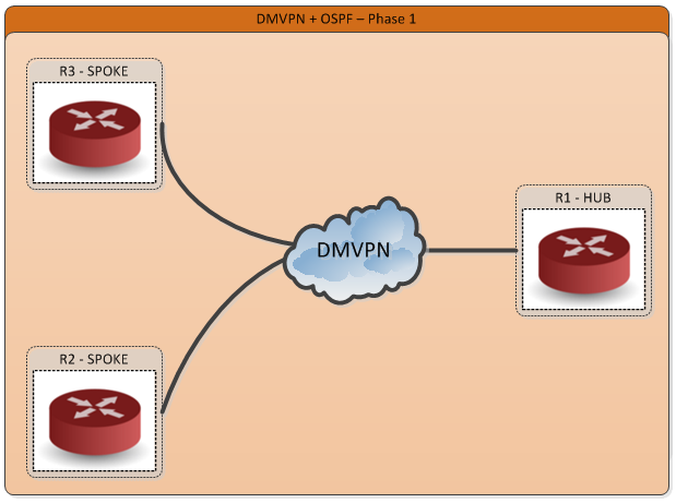
Here is our topology.
 R1#sh run int gig1.151
 Building configuration...
 Current configuration : 126 bytes
 !
 interface GigabitEthernet1.151
  description Internet_Facing
  encapsulation dot1Q 151
  ip address 1.1.1.1 255.255.255.0
 end
 !
 R1#sh run int lo100
 interface Loopback100
  ip address 10.10.10.1 255.255.255.255
 end

 R2#sh run int gig1.151
 Building configuration...
 Current configuration : 126 bytes
 !
 interface GigabitEthernet1.151
  description Internet_Facing
  encapsulation dot1Q 151
  ip address 1.1.1.2 255.255.255.0
 end
 !
 R2#sh run int lo100
 interface Loopback100
  ip address 10.10.10.2 255.255.255.255
 end

 R3#sh run int gig1.151
 Building configuration...
 Current configuration : 126 bytes
 !
 interface GigabitEthernet1.151
  description Internet_Facing
  encapsulation dot1Q 151
  ip address 1.1.1.3 255.255.255.0
 end
 !
 R3#sh run int lo100
 interface Loopback100
  ip address 10.10.10.3 255.255.255.255
 end
Ping and verify basic Layer 3 connectivity between the routers.
 R2#ping 1.1.1.1
 Type escape sequence to abort.
 Sending 5, 100-byte ICMP Echos to 1.1.1.1, timeout is 2 seconds:
 !!!!!
 Success rate is 100 percent (5/5), round-trip min/avg/max = 3/3/4 ms
 R3#ping 1.1.1.1
 Type escape sequence to abort.
 Sending 5, 100-byte ICMP Echos to 1.1.1.1, timeout is 2 seconds:
 !!!!!
 Success rate is 100 percent (5/5), round-trip min/avg/max = 3/3/4 ms
Next let's move onto configuring the DMVPN including NHRP parameters on all 3 routers. We will use the private subnet 192.168.1.0/24 for the DMVPN tunnel.
 R1#sh run int tun0
 Building configuration...
 Current configuration : 263 bytes
 !
 interface Tunnel0
  ip address 192.168.1.1 255.255.255.0
  no ip redirects

!!--Set the MTU to account for the GRE / IPSEC overhead
  ip mtu 1400

!!--Optional NHRP Authentication
  ip nhrp authentication AUTH
  ip nhrp map multicast dynamic

!!--NHRP network-id must match on all routers
  ip nhrp network-id 1
  ip tcp adjust-mss 1360
  tunnel source GigabitEthernet1.151
  tunnel mode gre multipoint
 end

 R2#sh run int tun0
 Building configuration...
 Current configuration : 291 bytes
 !
 interface Tunnel0
  ip address 192.168.1.2 255.255.255.0
  ip nhrp authentication AUTH
  i
!!--Map the NHRP Next hop server to the NBMA address of the HUB
  ip nhrp map 192.168.1.1 1.1.1.1
!!--Remember to do map multicast to HUB NBMA address (not the tunnel address) or else routing protocols will not work
  ip nhrp map multicast 1.1.1.1
  ip nhrp network-id 1
  ip nhrp nhs 192.168.1.1
  ip tcp adjust-mss 1360
  tunnel source GigabitEthernet1.151
  tunnel destination 1.1.1.1
 end

 R3#sh run int tun0
 Building configuration...
 Current configuration : 291 bytes
 !
 interface Tunnel0
  ip address 192.168.1.3 255.255.255.0
  ip nhrp authentication AUTH
  ip mtu 1400
  ip nhrp map 192.168.1.1 1.1.1.1
  ip nhrp map multicast 1.1.1.1
!!-Make sure network-id matches on all the routers
  ip nhrp network-id 1
  ip nhrp nhs 192.168.1.1
  ip tcp adjust-mss 1360
  tunnel source GigabitEthernet1.151
  tunnel destination 1.1.1.1
 end
At this point we should full tunnel-to-tunnel-end connectivity.
 R1#ping 192.168.1.2
 Type escape sequence to abort.
 Sending 5, 100-byte ICMP Echos to 192.168.1.2, timeout is 2 seconds:
 !!!!!
 Success rate is 100 percent (5/5), round-trip min/avg/max = 3/4/6 ms

 R1#ping 192.168.1.3
 Type escape sequence to abort.
 Sending 5, 100-byte ICMP Echos to 192.168.1.3, timeout is 2 seconds:
 !!!!!
 Success rate is 100 percent (5/5), round-trip min/avg/max = 3/4/5 ms

 R1#show ip nhrp dynamic
  192.168.1.2/32 via 192.168.1.2
   Tunnel0 created 00:12:18, expire 01:49:03
   Type: dynamic, Flags: unique registered used nhop
   NBMA address: 1.1.1.2
  192.168.1.3/32 via 192.168.1.3
   Tunnel0 created 00:09:29, expire 01:50:31
   Type: dynamic, Flags: unique registered used nhop
   NBMA address: 1.1.1.3
Keep in mind that this is DMVPN Phase 1 and as such dynamic spoke-to-spoke tunnels are not created. Therefore, all traffic between the spokes must go through the HUB. Here is a traceroute from R2 to R3 showing that the packets are indeed routed through the HUB.
 R2#traceroute 192.168.1.3
 Type escape sequence to abort.
 Tracing the route to 192.168.1.3
 VRF info: (vrf in name/id, vrf out name/id)
  1 192.168.1.1 4 msec 4 msec 4 msec
  2 192.168.1.3 4 msec * 5 msec
 R2#show ip nhrp static
 192.168.1.1/32 via 192.168.1.1
   Tunnel0 created 00:11:51, never expire
   Type: static, Flags:
   NBMA address: 1.1.1.1
Now that we have DMVPN Phase 1 working end-to-end, let's configure OSPF on the tunnel interface and advertise the routers Loopbacks.
 R1#sh run | sec ospf
 router ospf 1
  network 10.10.10.1 0.0.0.0 area 0
  network 192.168.1.0 0.0.0.255 area 0

 R2#sh run | sec ospf
 router ospf 1
  network 10.10.10.1 0.0.0.0 area 0
  network 192.168.1.0 0.0.0.255 area 0

 R3#sh run | sec ospf
 router ospf 1
  network 10.10.10.1 0.0.0.0 area 0
  network 192.168.1.0 0.0.0.255 area 0
When you first enable OSPF on all the routers, if you have console logging turned you will start to notice tons of these error messages on R1 ...
 %OSPF-5-ADJCHG: Process 1, Nbr 1.1.1.2 on Tunnel0 from EXSTART to DOWN, Neighbor Down: Adjacency forced to reset
 %OSPF-5-ADJCHG: Process 1, Nbr 1.1.1.3 on Tunnel0 from EXSTART to DOWN, Neighbor Down: Adjacency forced to reset
The reason that these error messages appear on R1 is because the tunnel interface on R1 is set to "tunnel mode gre multipoint" and when you enable OSPF on a tunnel interface the default OSPF network type is point-to-point. When OSPF network type is set to point-to-point the router is only expecting to be peered with one router. However, R1 is receiving OSPF hellos from multiple routers (R2 and R3). To fix this error, you can go to R1 and change the OSPF network type to point-to-point multipoint at which point the error messages will disappear.
 R1(config)#int tun 0
 R1(config-if)#ip ospf network point-to-multipoint
 R1(config-if)#end
However, you will notice that the adjacency between the routers is still not up and running. This is because the default timers for point-to-multipoint on R1 differs from point-to-point OSPF network type on R2 and R3 (R2 and R3 tunnel interfaces are set to tunnel mode gre vs R1's tunnel interface being set to tunnel mode GRE multipoint). Recall that hello / dead timers are one of the parameters that must match in order for routers to form OSPF adjacency.
 R1#sh ip os int tun0
 Tunnel0 is up, line protocol is up
  Internet Address 192.168.1.1/24, Area 0, Attached via Network Statement
  Process ID 1, Router ID 150.1.1.1, Network Type POINT_TO_MULTIPOINT, Cost: 1000
  Topology-MTID  Cost  Disabled  Shutdown   Topology Name
     0      1000   no     no      Base
  Transmit Delay is 1 sec, State POINT_TO_MULTIPOINT
  Timer intervals configured, Hello 30, Dead 120, Wait 120, Retransmit 5
   oob-resync timeout 120
   Hello due in 00:00:29
  Supports Link-local Signaling (LLS)
  Cisco NSF helper support enabled
  IETF NSF helper support enabled
  Can be protected by per-prefix Loop-Free FastReroute
  Can be used for per-prefix Loop-Free FastReroute repair paths
  Index 1/1, flood queue length 0
  Next 0x0(0)/0x0(0)
  Last flood scan length is 1, maximum is 1
  Last flood scan time is 0 msec, maximum is 0 msec
  Neighbor Count is 0, Adjacent neighbor count is 0
  Suppress hello for 0 neighbor(s)
 R2#show ip os int tun 0
 Tunnel0 is up, line protocol is down
  Internet Address 192.168.1.2/24, Area 0, Attached via Network Statement
  Process ID 1, Router ID 150.1.2.2, Network Type POINT_TO_POINT, Cost: 1000
  Topology-MTID  Cost  Disabled  Shutdown   Topology Name
     0      1000   no     no      Base
  Transmit Delay is 1 sec, State DOWN
  Timer intervals configured, Hello 10, Dead 40, Wait 40, Retransmit 5
   oob-resync timeout 40
We can solve this one of 3 ways.
- We can change the OSPF network type on R2 and R3 to be point-to-multipoint which will auto adjust the OSPF hello/dead timers to match up with R1 (default p2m hello 30 / dead 4 x 30 = 120).
- We can change the timers on R1 to match with R2 and R3 (default p2p hello 10 / dead 4 x 10 = 40)
- We can change the timers on R2 and R3 to match R1(default p2m hello 30 / dead 4 x 30 = 120).
 R2#conf t
 R2(config)#int tun0
 R2(config-if)#ip os network point-to-multipoint
 R3#conf t
 R3(config)#int tun0
 R3(config-if)#ip os network point-to-multipoint
Or
 R1(config)#int tun0
 R1(config-if)# ip ospf hello-interval 10
 R1(config-if)#end
 R1#
Or
 R2(config)#int tun0
 R1(config-if)# ip ospf hello-interval 30
 R1(config-if)#end

 R3(config)#int tun0
 R1(config-if)# ip ospf hello-interval 30
 R1(config-if)#end
 R1#
Once you use one of the methods mentioned above OSPF will come up between the routers. Now notice that the next hop is changed to R1's IP. For example, see below on R2 ... To get to R3 loopback from R2 the next-hop is set to R1's IP.
 R2#sh ip route 10.10.10.3
 Routing entry for 10.10.10.3/32
  Known via "ospf 1", distance 110, metric 2001, type intra area
  Last update from 192.168.1.1 on Tunnel0, 00:00:07 ago
  Routing Descriptor Blocks:
  * 192.168.1.1, from 3.3.3.3, 00:00:07 ago, via Tunnel0
      Route metric is 2001, traffic share count is 1
As I previously mentioned, OSPF is generally discouraged in a DMVPN design, however if you need to need to deploy OSPF with DMVPN, be sure to look out for these pitfalls.
Would you consider OSPF in a DMVPN design? If so, why?
Many more articles to come so ....
Please subscribe/comment/+1 if you like my posts as it keeps me motivated to write more and spread the knowledge.
No comments:
Post a Comment